As I mentioned in the previous blog post, I recently got my hands on a Canberra 2100 NIM Bin off of eBay. I am extermely lucky to get this piece of equipment so cheap, they quite often go for many hundreds of pounds depending on which which country the seller is based. The Supply itself consists of a quite unwieldy unit hanging off the back of the subrack unit as can be seen in Fig 1, in my DIY and too be completed 19inch rack. Ignore the logic analyser and KVM switch on top.
Unfortunately, once you get your hands on such a bin, if you want to go ahead and start playing around with whatever wild and wacky nuclear physics experiements, you will need to acquire the NIM Modules themselves. I'm not happy with the, just buy approach to all this stuff at the moment. Yes, it can be done, but it is getting increasingly expensive and these are very nice vintage pieces of equipment. The industry has already moved over to VME, PXIe, et al. long ago and though there are manfacturers out there, they sell units with an extremely high price tag. What is needed is an open-sourced, compatible bin/module that can hook up to whatever bin/modules someone aldready has. Better yet, a compatible system with it's own modules and bins, to hook up interchangeably with old stock or brand new systems. Bit of a word fart, but I hope that makes sense. Use the DOE_ER-0457T standard for NIM, readily avaiable; such as here!. Then make the CAD files and necessary hardware available to others.
- PGM - Module Connector
- PGB - Bin Connector
- NOTE - The only difference between these physically is the guide pin/socket hardware
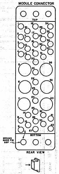
So. First thing is how to interface with the BIN I already have. It provides no logic backplane to the PGBs, instead only offering a bussed connection to the power supply itself. The 2100 Bin/PSU has the following contacts available, the others are unpopulated. See the NIM standard above for their placement.
- 10 -> +6V
- 11 -> -6V
- 16 -> +12V
- 17 -> -12V
- 28 -> +24V
- 29 -> -24V
- 33 -> 117VAC Hot [You love to see it]
- 34 -> Power Return GND
- 41 -> 117VAC Neutral
- 42 -> High Quality GND
This meets the minimum requirments placed on the bins by the standard (p25 Fig 6). On top of this are the guide pins and sockets, all used for alignment of the modules but some provide local grounding as well.
For someone to make one module themselves, this means there is a significant number of items on the BOM, all of which, if you follow the standard in buying from AMP (TE Connectivity), cost a horrendous amount of money. But yet again everything is MILSPEC, this is an American Cold War standard after all. I was quite surprised that the part numbers listed under AMP, are all still active and searchable through TE Connectivity's website. See here, the Diallyl Phthalate PGM connector housing (204186-5) for a cool $122 if you order specially from them. Things do get better if looking at new compatible products such as (202515-1) for £16.40 in single quantities from Digikey. I haven't seen better than this but we haven't even covered the contacts yet either, nor the four guide pins/sockets! Easily, for just one module, it's going to cost upwards of $100, just in connecting hardware. Compare that to just one DIN-41612 male connector for a couple quid, which has nearly a hundred contacts, better yet a PCIe card edge connector.
This is the largest barrier to entry I can see and I want to make it easier to play around with this cool stuff.
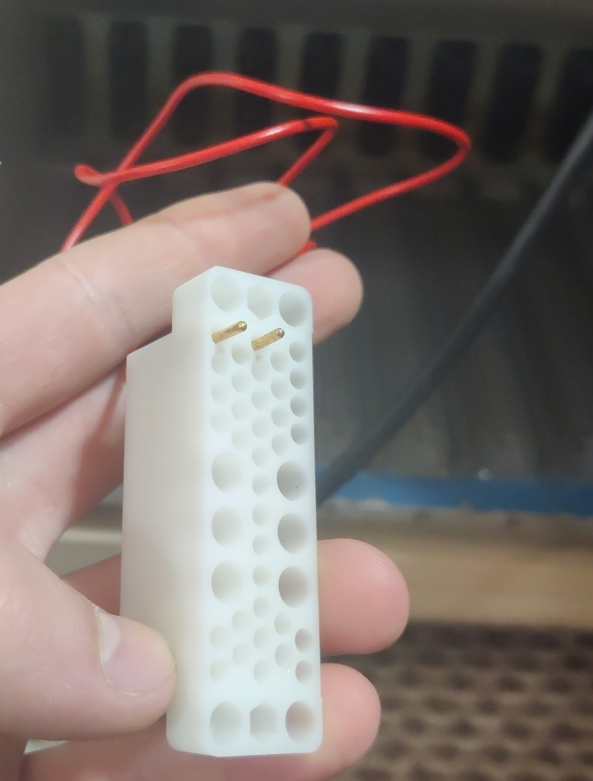
I started by reverse engineering a CAD file from the original DOE_ER-0457T standard, I wanted to avoid using those available from TE for copyright reasons. As far as I know, there shouldn't be an issue with releasing drawings derived from the standard itself. After doing this and printing a sample myself, I sent off some samples to JLCPCB to get them 3D printed in a better quality. I got the samples back today in three different materials (SLA 6060, 8000 and 9000). All came out looking great and look much better than my humble attempt.
I was warned when ordering them that the minimum wall thickness was too small and could cause issues but they all seem grand. The 6060 beats the other two in my comparison of them, with less thermal warping, sharper features, dimensional accuracy and less swarf. That is assuming that these differences have arrisen from the material choice and not a difference in manufacturing process. Now I have a connector housing with which to experiment with different contacts, hopefully to find ones at a lower price. I'm not against changing the CAD file of the connector however to change it to accomodate slightly different style contacts which require different mounting considerations. As long as, to the user, there is compatibility with other equipment, I don't see why this couldn't be done, especially as these can be 3D printed in different styles with ease.
The contacts I went with for the test piece shown in the first image are TE 1-66359-6, these are the gold versions and are hance a bit more expensive, Digikey had no stock at the time. I have the female counterparts (tin plated) TE 1-66598-2. The fit is very good with these contacts, even with the thin internal mating surfaces in the connector. They are extremely thin for FDM printing but accurate to the drawings for now.
The fit of the connector in the backplane of my Bin is very good and I am tempted to just use the contacts for alignment, etc, but with the added weight of an entire module it may not be enough. Buying the guide pins and sockets for each connector is still quite expensive so it may be beneficial to 3d print these, relying solely on the smaller ground contacts for good grounding. I'll need to experiment with this in a future order